Workshop Entry No. 03
Flux — Driver Assembly
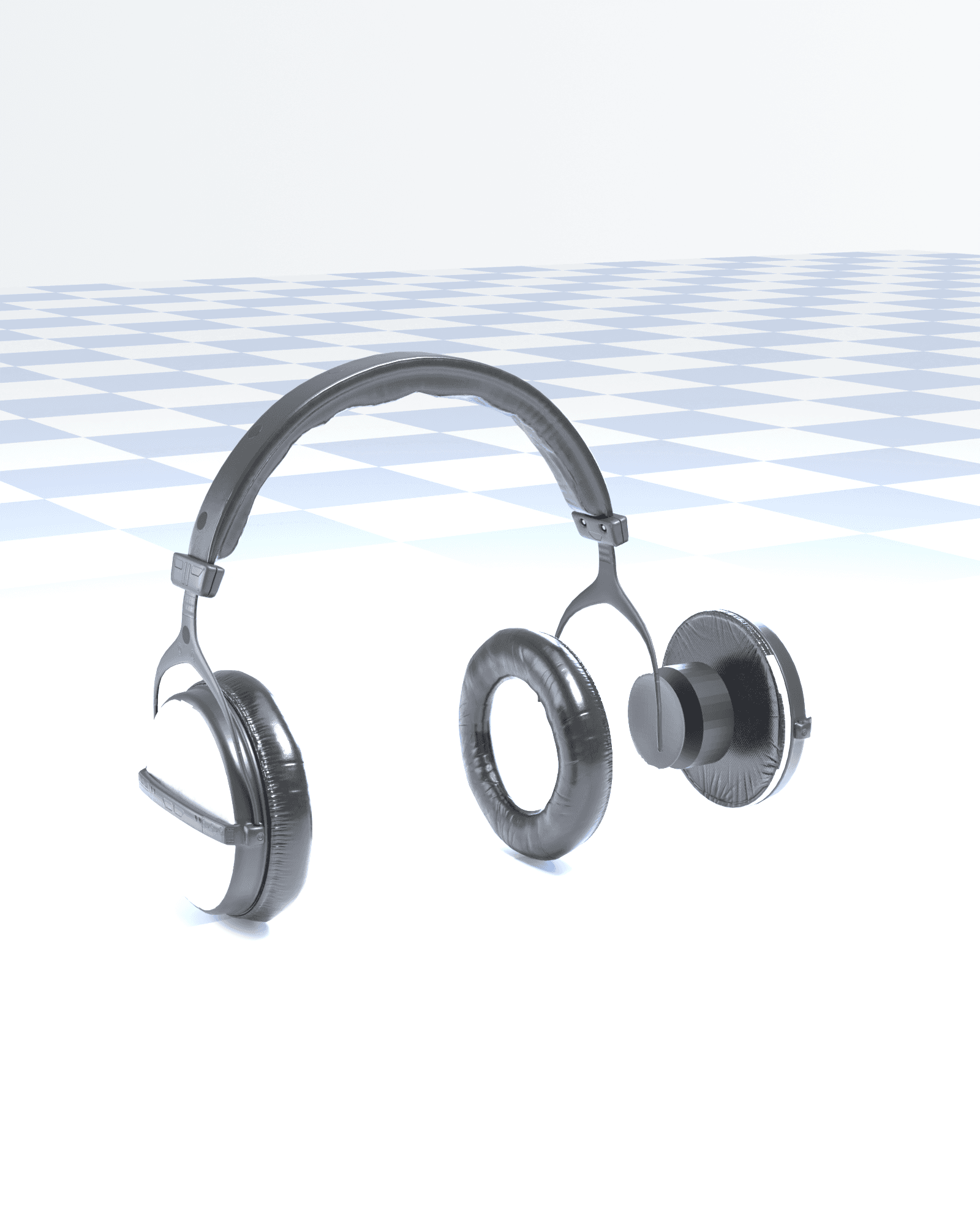
A technical walkthrough of one driver, taken apart in the order a bench tech would open it: cushion off, diaphragm exposed, coil and magnet underneath, yoke last before the shell.
Scope
Right ear cup only, cushion to shell, along a single axis. The left cup, headband and slider stay assembled — shown for context, not covered in this section.
 123456
FIG. 5.1 — Flux driver assembly, exploded along the ear-to-ear axis. Right cup only; left cup, headband and slider stay assembled for context.
Key to Fig. 5.1
- 1Cushion
- −18.3 mm, toward the listener
- 2Diaphragm
- +20.3 mm
- 3Voice coil
- +35.5 mm
- 4Magnet
- +47.7 mm
- 5Yoke
- +48.7 mm
- 6Shell
- +71.1 mm
Teardown Sequence — Steps 1 to 3 of 6
Cushion
Pulled 18.3 mm toward the listener, the opposite direction from every other part in this section. That is the one move that opens a real gap without touching the shell.
Offset −18.3 mm, toward the listener
FIG. 5.2 — Cushion, pulled back from the shell
Diaphragm
Dome and surround, the part that actually moves the air. Thin on its own — everything that follows in this section exists only to drive it.
Offset +20.3 mm
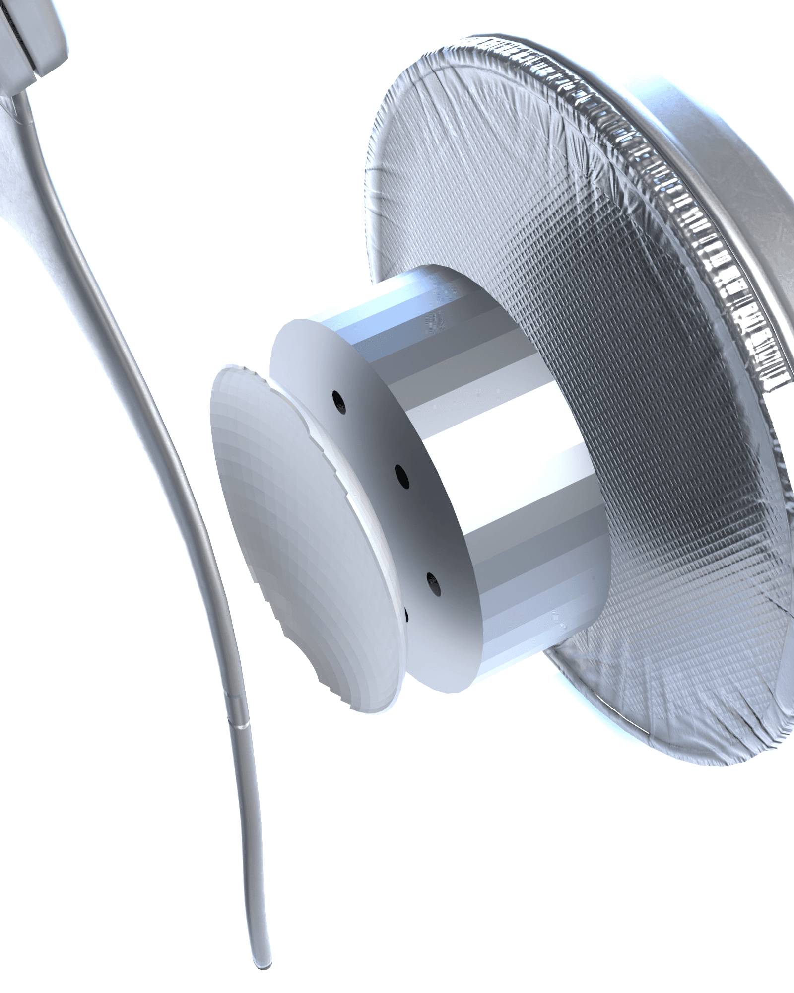
FIG. 5.3 — Diaphragm dome, driver macro
Voice coil
A wound copper helix, 22 turns, built as a real spin in the model and never flattened to a decal. It sits inside this housing, under the yoke's outer wall, and does not clear the edge on its own.
Offset +35.5 mm
FIG. 5.4 — Coil housing, seated under the yoke wall
Teardown Sequence — Steps 4 to 6 of 6
Magnet
The field source. Real geometry, separated and confirmed in the model, but fully inside the same housing as the coil at this camera angle — not every part in a driver wants to be photographed from the front.
Offset +47.7 mm
FIG. 5.4 — Same housing as the coil, magnet inside it
Yoke
Magnetic housing with six real vent holes, cut as a boolean through the mesh in the model, not painted on afterward. The holes are the difference between moving air and just moving pressure.
Offset +48.7 mm
FIG. 5.5 — Yoke vent holes, real boolean cut
Shell
Outer housing, the layer furthest from the ear once the cup is open. In the assembled pair, everything in this section lives inside it, out of sight.
Offset +71.1 mm
FIG. 5.6 — Shell, open-mesh grille
Assembly Spec — Separation
- Axis
- X local, ear to ear
- Unit spacing
- 20.3 mm per rank
- Total spread
- 89.4 mm, cushion to shell
- Spread ratio
- 4.2x cup depth
- Coil winding
- 22 turns, real helix
- Venting
- 6 holes, real boolean cut
FIG. 5.7 — Driver macro, reference frame. Same photograph used for FIG. 5.3 through FIG. 5.5, shown here uncropped.
Note
Flux is a self-initiated concept by Lokebox Studio — real geometry pulled apart along one axis, no maker or store behind it. The same driver appears elsewhere in this portfolio fully assembled and closed; this section only covers how it comes apart.
End of Section 5